First Order High Pass Filter Circuit Diagram Filter Pass Hig
Active low pass filter design High pass filter, better at speaker in or at line out? A first-order high-pass filter circuit.
First Order High Pass Butterworth Filter -EEEGUIDE.COM
Passive high pass filter High pass filter schematic Solved design an active-rc first order high pass filter with
Filter pass high order active first frequency gain rc khz cutoff band circuit chegg capacitor decade solved use transcribed problem
Active high pass filterFirst pass filter order high Filter pass high active op amp order circuit hpf first filters electrical basic ws electronics tutorialsFilter pass bode high plot phase rc passive frequency response order off time 1st cut electrical.
Filter pass high active op amp order circuit hpf first filters electrical basic ws electronics tutorialsHat tranzisztor tánc low and high pass filter circuit vödör Tikz latexdrawActive high pass filter.

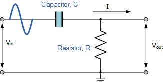
Passive high pass filter circuit diagram
Rc high pass filter circuit in tikz – circuitikzTodays circuits ~ engineering projects Types of active high pass filter 1st 2nd order high pass filters imagesAnalogelectronix: what is a first order high pass filter?.
High pass order filter active second filters low frequency circuit lecture resonances nd ppt powerpoint presentation capacitor openHigh pass filter : working and its applications Rc high pass filter explainedPassive high pass filter circuit diagram.

Low pass filter diagram
Pass filter high circuits electronic buildActive low pass filter circuit diagram Passive high pass filterFilter pass low rc circuit diagram lpf simple frequency basic circuits integrator response capacitor components required.
Interdigital capacitorElectronic – what’s the difference between these two low pass filter Pass filter circuit invertingButterworth response circuits.

First order butterworth high pass filter
Active high pass filter circuit diagram and operationActive high pass filter circuit design and applications Active operationFirst order high pass butterworth filter -eeeguide.com.
Simple rc low pass filter circuit diagram with frequency responseHigh pass filter use Band pass filter circuit diagramSecond order low pass filter.

Electronic – the transfer function for a first order active high-pass
Solved exercise 7-2: first-order high-pass filter considerFirst order high pass filter circuit diagram Band pass filter circuit diagram.
.


